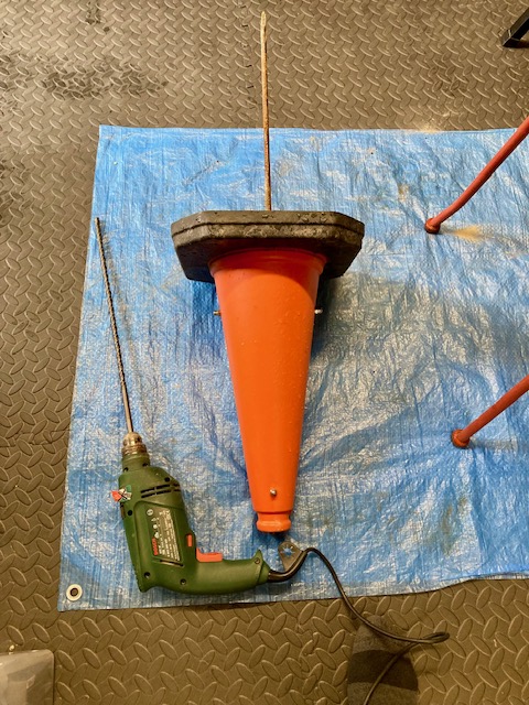
Cars repeatedly park on the grass verge opposite our driveway, blocking access. Commercial bollards proved ineffective, so I fabricated a pair of reinforced, ground-anchored concrete traffic cones for around £12 each.
Background
Parking bollards are easily moved out of the way, and, on occasion, driven over by determined car owners. The introduction of a day’s minimum charge rate in the nearby car park has turned a moderate problem into a severe problem at peak times. This tends to be at public holidays, school holidays, and when the sun first appears in Spring.
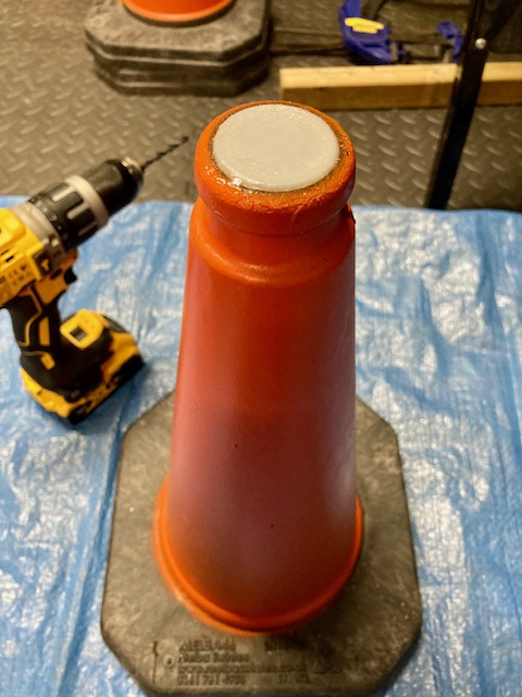
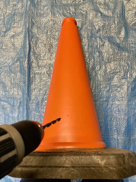
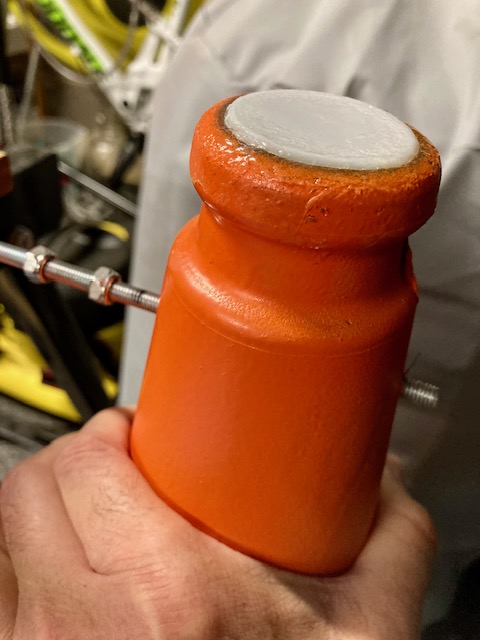
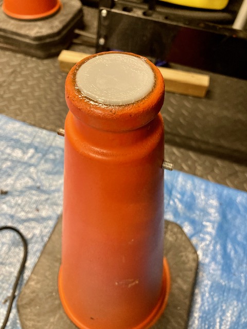
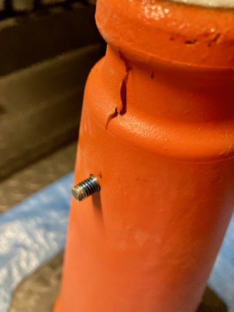
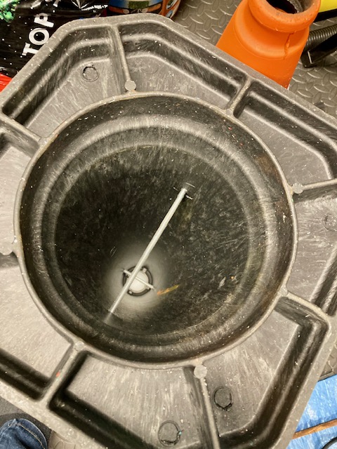
A recycled milk carton screw cap provided the perfect bung. 6mm holes were drilled at 6cm from the top and bottom at opposite sides.
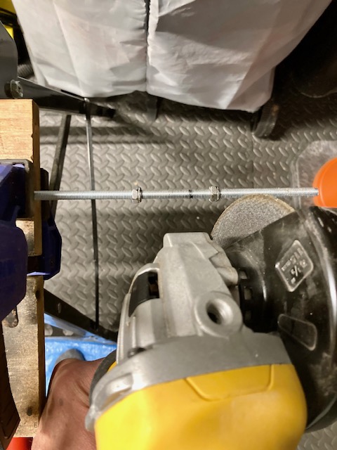
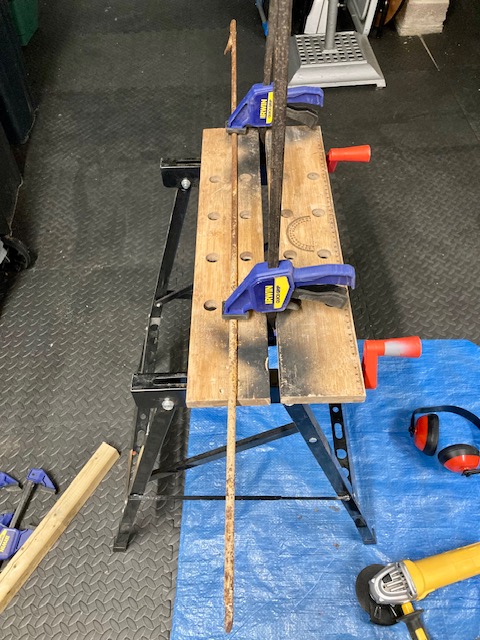
Threaded Bar Cut to Length
The threaded bar was cut to length using an angle grinder. The M6 steel nuts are screwed onto the threaded bar. It’s important to screw the nuts either side of where you plan to cut the threaded bar. This ensures the thread is reformed correctly by unscrewing over the newly cut end. It helps to file down each edge to smooth any ragged ends / swarf. I use the mole grips to turn the nuts over the thread.
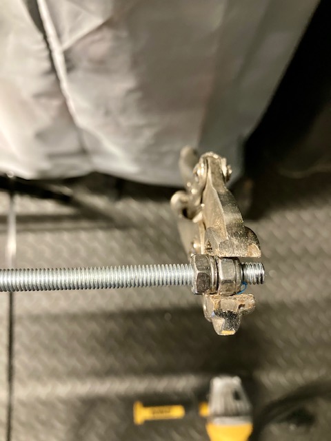
Dome Nut
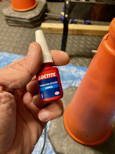
The M6 dome nut is screwed on with thread lock to prevent loosening. The dome nut provides a safer, non-sharp finish.
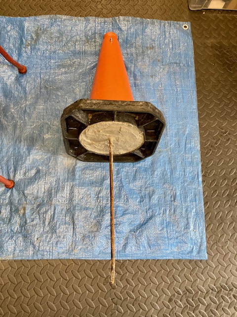
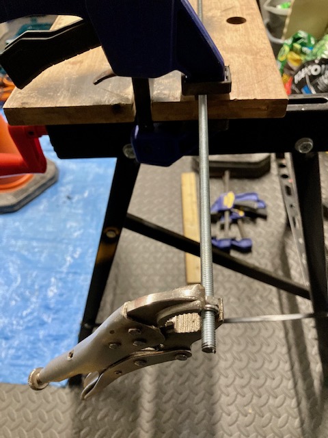
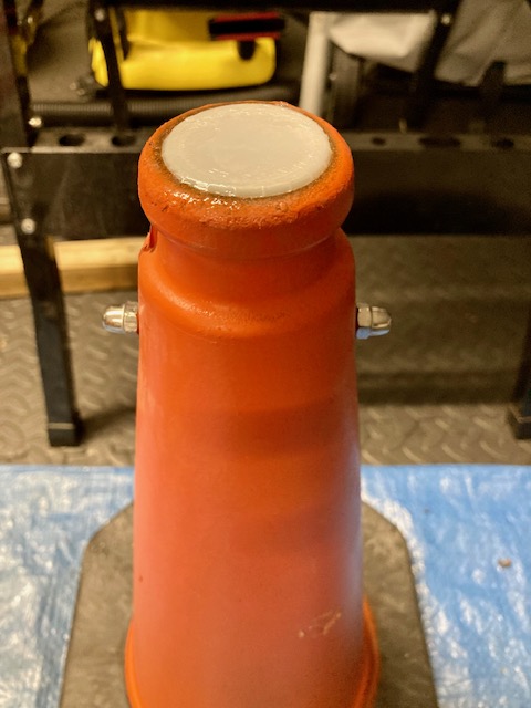
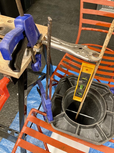
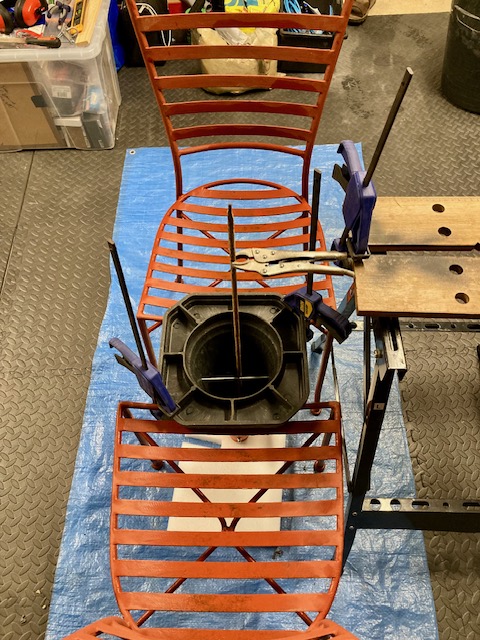
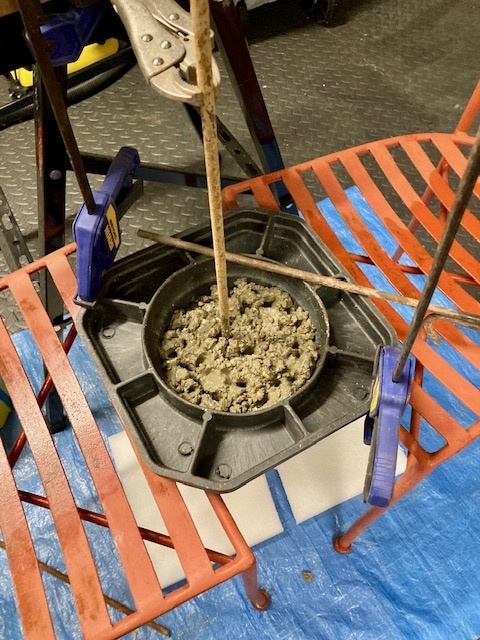
Preparing the Spike
Both threaded bars are inserted and the internal spike is cut to length and tied into the threaded bar. A spirit level is used to keep everything at right angles.
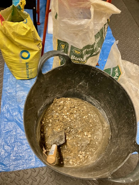
The Cement Mix
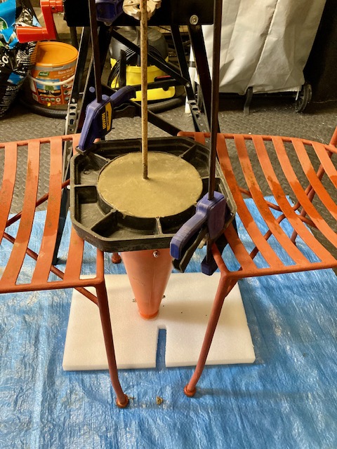
The traffic cone is now ready for the cement mix. The recommended mixture is 1 part cement: 2 parts sharp sand: 3 parts 10mm pea shingle. Just enough water is added but limited to ensure the mix sets strongly.
Lessons Learnt / Next Steps
Finding a bung (milk bottle top) to fit was lucky.
Safer use of the angle grinder. The spark fender can be pivoted around!
Once the concrete has been allowed to cure for two weeks, they will be installed.
This project converts an existing hot water immersion heater from a simple on / off manual switch to a configurable system with remote access. The goal was simple:
Keep the design safe
Keep it simple
Keep costs low
CAUTION: This blog documents the steps taken by a curious DIYer and may not be suitable for your use case. Electrical installations can be dangerous. Seek help from a professional electrician or plumber if you are at all unsure.
The Setup
The system consists of:
A Linky smart meter and consumer unit
A ballon d’eau chaude (immersion heater)
Linky Smart Meter & Consumer UnitBallon d’eau chaude sanitaire (immersion heater)
Options Considered
Option A — Smart switch at the heater Install a smart switch directly inside the immersion heater.
Option B — Smart switch in the consumer unit Control the heater circuit upstream using existing switching hardware.
Option C — Hire a professional Always sensible—but less appealing for a curious DIYer (and not always easy in France).
Chosen Approach
Option B was selected.
Option A requires a high-current smart switch (~16A for a 3000W heater) and opening up an old immersion heater—less desirable from a safety perspective.
Option B uses the existing relay (contactor), switching only the low-current control side, making it significantly safer.
Prerequisites
Before starting the installation, a couple of practical checks are performed.
WiFi Signal Strength
Since the smart switch relies on WiFi for control and scheduling, it’s important to ensure there is a reliable signal at the consumer unit.
Check signal strength using my phone while standing next to the consumer unit
A stable connection (at least 2–3 bars) is recommended
If the signal was weak, a WiFi extender or repositioning of the router may work.
An alternative approach is to install a Shelly smart switch that supports Zigbee or Matter.
Contacteur Jour/Nuit
In France, immersion heaters are often controlled by a Contacteur Jour/Nuit, designed to run during off-peak hours. This device is a type of electrical contactor.
It has 3 modes:
I → Always On
Auto → Controlled (normally by off-peak tariff)
0 → Always Off
In this setup, we use a standard EDF tariff, so the Auto function is unused. This makes it perfect for repurposing with a smart switch via terminals A1 and A2.
Some definitions:
Contactor → a specific type of relay designed for high-power loads (such as this immersion heater)
Relay → a general term for an electrically operated switch
Contacteur Jour/Nuit → the French term for a contactor with a control circuit (often tied to off-peak tariffs)
Contacteur Jour/NuitCircuit Breaker
Circuit Breaker
The heater circuit is protected by a dedicated breaker.
Conveniently:
It provides spare terminals for live and neutral
These are used to power the smart switch
Components
The following components were used to complete the installation. All are readily available and relatively inexpensive.
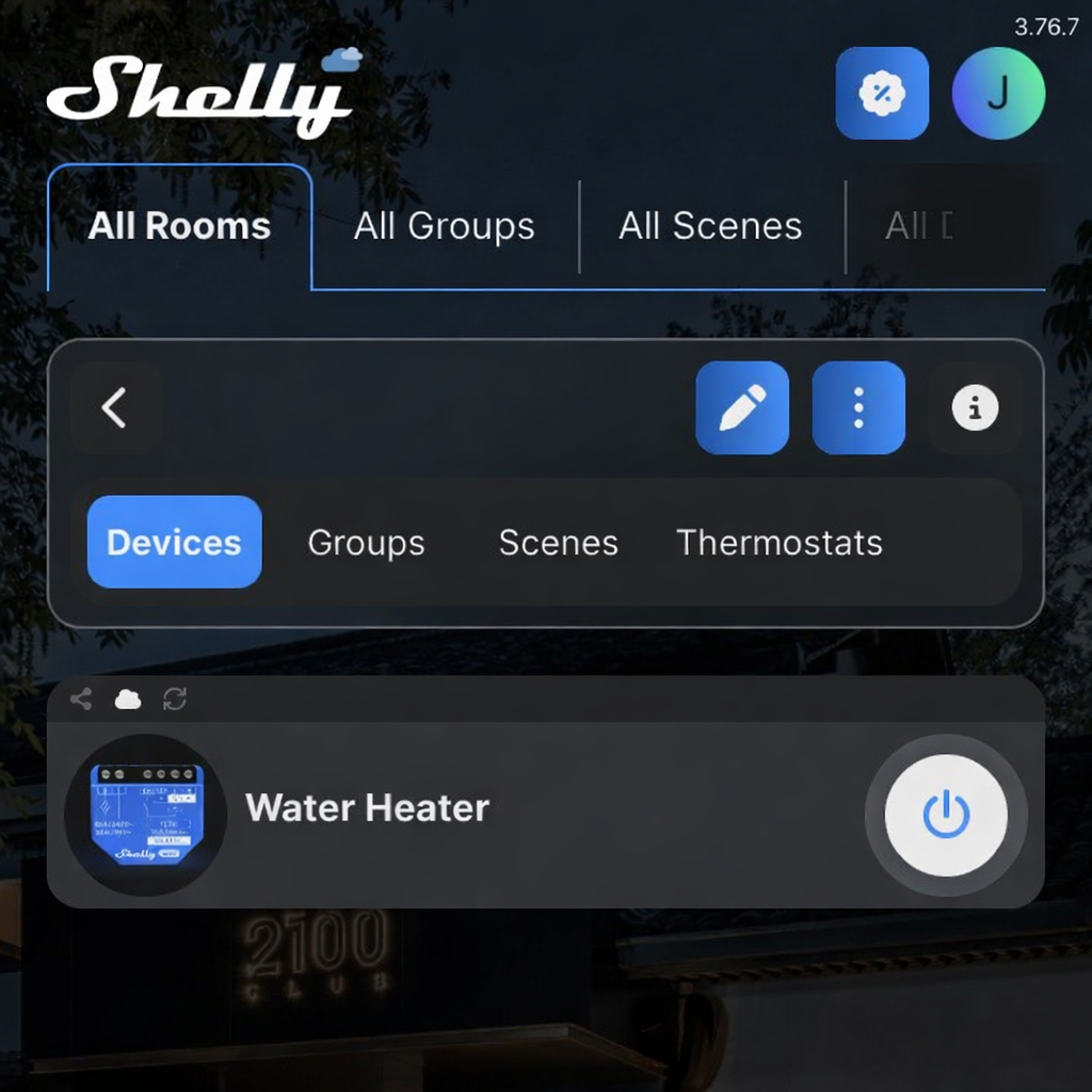
Shelly 1 Gen 3 – Smart Switch
A compact WiFi-enabled relay used to control the contactor. It supports dry contact operation, meaning it can switch a circuit without supplying power itself—ideal for safely controlling the low-current coil of the relay.
A 3D-printed DIN rail mount used to securely install the Shelly inside the consumer unit, keeping the wiring tidy and compliant with enclosure standards.
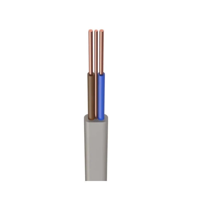
Standard domestic wiring cable, chosen to match the existing wiring within the consumer unit. Using consistent cable sizing helps maintain clarity and compliance.
This is my experience replacing a car battery for the first time on our 10-year old family wagon. Despite a number of long journeys, it was taking longer to start the engine. A wait of 5 seconds or more became normal.
3-Month Update: While replacing the battery significantly improved the situation, it didn’t completely resolve it. The root cause also involved a faulty start/stop button, which needed replacing. Since carrying this out, the car has worked perfectly with no further problems.
I decided to ‘pop the hood’ and measure the battery voltage using my multimeter. The overnight reading, when the battery was ‘cold’, showed 11.7 volts. When the engine was running, the reading was 14.3 volts. In summary:
14.3V – the alternator was doing its job, but,
11.7V – either the battery needs re-charging or replacing.
Given the age of the battery, it seemed pragmatic to replace it before attempting any further investigation.
Battery Options
Our VW Tiguan 2.0 TDI was supplied with a VARTA 12V AGM battery offering 68Ah capacity and start/stop capability. When entering the car registration plate into various websites I was presented with three options.
Halfords, £210 for supply and fitting (plus disposal of the old battery) for an own-brand battery with a 5-year warranty
Kwik Fit, £267 for supply and fitting (plus disposal) of a Bosch battery, 70Ah capacity with a 5-year warranty
Amazon, £130 for home delivery via Prime of the same Bosch battery above.
The decision was straightforward: how hard could it be to fit a car battery?* I would save a considerable amount, learn a bit about car maintenance plus avoid a trip to the garage.
*Spoiler alert, not quite the saving I first thought.
Research
The Bosch battery arrived within 24hrs from Amazon. Meanwhile, driving the car felt like playing Russian roulette. Would the current battery be strong enough to restart the engine and get us back home? So, the pressure was on to get the new battery installed as soon as possible.
The online investigation began in earnest. Advice was consistent: always disconnect the negative battery terminal first, and the positive last. Re-connect in the reverse order: positive first and finish with the negative. Then, another forum talked about coding the battery, and after a bit more research for our vehicle, the reality dawned that coding was a mandatory step. Hmm.
Battery Coding
Coding the car battery ensures the charge profile, managed by the car, is appropriate for the capacity, chemistry and age of the car battery. This avoids premature aging of the new battery.
Bosch!
I called our local independent tyres/ batteries/ MOT outfit to look at my options. The response was: ‘No, we wouldn’t code a battery we haven’t supplied and fitted ourselves’. It was unlikely Halfords or Kwik Fit would respond any differently. Hmm again.
OBD2
The £130 was a sunk cost. Sending the battery back to Amazon for a refund was not an option. I started to investigate OBD2 readers. OBD2, or On-Board Diagnostics II, is a standardised system in vehicles that monitors and reports on the performance of the engine and other essential components, primarily for emissions control. It allows mechanics to access diagnostic trouble codes (DTCs) and real-time data to troubleshoot issues effectively.
OBDeleven
Various forums recommended the OBDeleven brand of OBD2 readers for VAG cars. I ordered a ‘NextGen’ device from them directly. However, there is a catch, OBD2 readers are simply that – they read data only. I needed an OBD2 reader that can also write data back to the car’s computer. This requires a PRO subscription for a minimum one year period. Reluctantly, I order the OBDeleven reader plus the subscription for £88 (€100 with fast delivery).
ChatGPT explained that short car journeys over a few days, whilst the battery remains uncoded, are unlikely to cause premature aging of the battery.
Battery Fitment
Car batteries are heavy. The process takes 30 mins for a novice: access between the engine and the bonnet is restricted; the car’s battery box is designed to come apart but impossible to re-fit with only a single pair of hands. Duct tape was used to keep the positive terminal from getting in the way during re-fitment.
Once re-fitted, the dashboard lights up. The following problems were forewarned and resolved by a YouTube video:
Car clock needs resetting
The steering angle sensor needs resetting by steering full lock to the left, followed by full lock to the right
The passenger window had been left open during the battery change. The one-click up and down needs resetting by pushing and holding the button at full open (and full close) for 3 seconds.
Following these steps, the dashboard lights were all extinguished.
Battery Coding
The OBD2 reader arrives later than planned. An online account with OBDeleven is created. Finding the OBD2 port within the car is straight forward and registering the PRO subscription from the iPhone app takes seconds.
Tackling the code registration is fairly daunting given the ‘Long Adaptation’ coding is less than intuitive. There are different methods between vehicle manufacturers and age of vehicles within manufacturer. Sharing information with ChatGPT helped to confirm steps not easily found via website searches alone. A VW specialist would be required if the coding went wrong and the car was incapacitated.
Conclusion
Would I do it again? Yes, though it is disappointing that battery coding cannot be managed directly from a car’s instrument panel. However, now I have an OBD reader, one-year of PRO subscription, plus an old car battery that can be disposed of for £8 at a recycling facility. Total Cost = £210 (130+88-8). The same cost as a fitted, Halfords branded battery.
Anyone need a car battery coding? Only 350 days of the OBDeleven subscription to go. Some of their One-Click Apps look interesting.
This is a project to replace a standard heating controller (Horstmann H37XL) with the HIVE smart heating control system.
We have an oil-fired boiler connected to a hot water tank, servicing two heating zones. The radiator system is open-vented, and motorised valves are controlled by the heating system.
Limited information could be found on the internet for this specific use case, therefore, I capture my experience here for reference. The key benefits for this upgrade are:
support for remote heating control, and,
a lower heating bill.. hopefully.
CAUTION: This blog documents the steps taken by a curious DIYer and may not be suitable for your use case. Electrical installations can be dangerous. Seek help from a professional electrician or plumber if you are at all unsure.
Background
User Request: The user adjusts the thermostat to request heat, signalling the control system to initiate the heating process.
Motorised Valve Operation: The heating control system activates the motorised valves associated with the relevant heating zones, allowing water to flow into the radiators.
Pressure Drop: As the motorised valves open, the flow of water changes. In an open-vented system, this can lead to a decrease in overall system pressure.
Pump Activation: The pressure drop, along with the demand for heat, triggers the pump to start circulating water through the system.
Boiler Ignition: The pump activation signals the oil-fired boiler to ignite and heat the water, ensuring that the warm water reaches the opened radiators and provides the requested heat.
Before
After
Ingredients
HIVE Thermostat Mini for Heating Control & Hot Water with Nano 3 Hub
HIVE Thermostat Mini for Heating Control Multizone (Hubless)
Blank Plate 1 Gang * 2
Twin & Earth Cable (6242Y) 1.5mm Coil
WAGO 221 Compact Lever Connectors (2, 3 & 5-way)
TP-Link TL-PA717 1-Port Gigabit Powerline Kit.
Process
Switch off the heating system at the isolation switch (left of existing controller), remove the controller and reveal the wiring plate. Check there is no voltage across the wires using my Fluke 1AC-II voltage tester. Safety first!
Current Setup
To make sense of the wires, I search for wiring diagrams and used ChatGPT to validate any conclusions. We have from left to right:
2 earth wires sharing the same connection (yellow/green)
Then, 4 neutral wires (3 blue and a single black)
Then, 4 live wires (3 red and a single brown)
Then, 2 wires (blue and yellow) in switched live terminal L1
Then, 1 wire (yellow) in switched live terminal L3
Finally, 1 wire (red) in switched live terminal L5
Interpretation
The mix of wire colours causes confusion, plus the two wires on L1 did not make sense. ChatGPT was helpful, though it became fixated on a ‘standard’ implementation which was inconsistent with the wiring diagram below. Eventually, this is what I surmised:
It is quite common for plumbers to use non-standard wiring colours. Great!
There is an existing, wired frost prevention thermostat. This will bypass the controller and switch the heating on automatically if the room temperature drops too low.
Therefore, the additional switched live wire in terminal L1 is likely to come from the frost prevention thermostat. I plan to keep this in the new system since it monitors the temperature in another downstairs room.
The wiring diagram below suggests we have central heating zone 1 (CH1), central heating zone 2 (CH2) and hot water (HW) in terminals L1, L3 and L5 respectively.
Simplify the Wiring
The next step was to label and simplify the wiring. At this point it was not certain that the HIVE system would work as intended, therefore it was important to be able to reverse any changes and call a professional, if needed!
The following picture shows: a) the switched wires labelled with masking tape, and b) WAGO connectors added to reduce the number of wires required for the existing backplate.
Test Run
An initial test run of the dual zone HIVE receiver (HW + CH1) is performed.
CH1 – central heating zone 1 could not be started from the boost button. This was resolved by remembering that the existing room thermostat needs to be on maximum to ensure this is not overriding the HIVE thermostat.
HW – in addition, the hot water boost did not start up. The light came on but the boiler did not fire up.
I stopped the test run and re-installed the original controller. Subsequently, I believe that the hot water was already above the target temperature in the hot water tank. I could have run the hot water tap at the kitchen sink to lower the temperature and trigger the boiler to fire up.
The test run results were sufficiently encouraging to continue onto the next step of the project.
Mounting the HIVE receivers
Significant time was spent working out how to mount both HIVE receivers neatly to the wall in the same space as the existing controller. Once I had identified that the existing backboxes were two adjacent singles* then I focussed on how to mount the HIVE back plates to the 1-gang, blank plates.
*Initially I assumed a 2-gang, blank plate would work. It transpires that a 2-gang plate is not the same width as two 1-gang plates!
The correct 1-gang blank plates were purchased. I test fit the two receivers side-by-side to find that they cannot fit within each plate. So, the receivers are mounted flush to the left side ensuring the adjacent switch can be accessed in the future. I mark areas for cutting & drilling using masking tape.
The central holes are cut first. Then, holes for the mounting screws are drilled. One of the blank plate cracks under the pressure. A more gentle technique is applied the next time round.
A test fit identifies that the HIVE back plate must be fitted after each blanking plate has been screwed to the wall. This is because the HIVE back plate masks the holes that secure the blanking plate to the wall. In addition, I did not want to drill through the HIVE back plate to expose these holes in case this weakened it. Two challenges present themselves:
#1 The mounting bolts (sourced from my stash) for the HIVE back plate are very short at 12mm long. However, they need to be shorter to prevent the bolt from fouling the wall tiles where they sit close to the edge. The bolt is reduced to approximately 9mm by: threading three nuts to the top of the bolt; trapping the bolt in a mole grip; clamping the mole grip to my workbench; then using a hacksaw to cut 3mm off the end; the three bolts are then unscrewed to ensure the thread is reformed correctly following the cut. A lot of effort for a very small cut!
#2 The nut for the mounting bolt will be very difficult to access when the blank plate is affixed to the wall. I decide to form a captive nut by setting it in 2-part epoxy putty (Milliput) at the back of the plate. I chose this over super glue since it is difficult to prevent the glue spreading onto the thread of the nut. You will see the captive nuts in the bottom left and top right of the picture.
Final Steps
Screw the blank plate to the wall
Screw the HIVE back plate to the blank plate
Pull the wires through and attach to the correct terminals on the HIVE back plate
Terminal Mappings
#
Zone Description
Horstmann H37XL
HIVE Receiver
HIVE Terminal
1
CH1
L1
Dual Zone
L4
2
HW
L5
Dual Zone
L3
3
CH2
L3
Single Zone
L4
4
Jumper cable
N/A
Single Zone
L to L1
Switch the electricity on at the isolation switch
Install the Powerline kit to ensure a reliable internet connection from the home router to the HIVE hub.
Follow these instructions from HIVE to connect each receiver to their thermostat and the HIVE app.
Finishing Touches
Mount the HIVE hub on the wall and cable-tie the wires out of the way
Close the circuit on the existing room thermostats, upstairs and downstairs
Fix the new wireless thermostats to the wall in the same location
Backplate to the existing wired thermostatRemove the backplateAdd a WAGO connector to join the Permanent Live to Switched LiveMount the HIVE thermostat in the existing screw holes
Final Steps
Test the wired frost prevention thermostat
Make a crib-sheet advising users how to operate the new HIVE Mini Multi-Zone heating system. Laminate and fix to the wall above the HIVE receivers.
A fantastic weekend catching up, and....it’s great to see your new home. Congratulations!On Sunday we travelled onto Mudeford Sandbank near Bournemouth